RFID Antennas & Inlays
Antennas do most of the work in an RFID system: the tag antenna captures energy and sends data back, and the reader antenna shapes where tags can be read. This chapter explains tag antenna design, inlay types, reader antenna specifications such as polarisation, gain and beamwidth, cabling and practical placement.
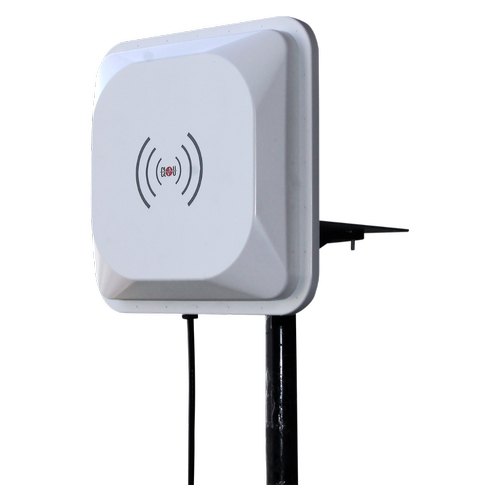
- A tag antenna is matched to its chip and tuned for a frequency band and the material it will sit on.
- Metal and liquids detune tag antennas and absorb or reflect energy - use tags designed for those surfaces.
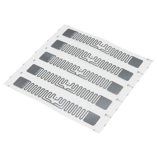
- An inlay is the chip plus antenna on a thin film; dry, wet and paper-face labels are different conversions of it.
- Circular polarised reader antennas read tags in any rotation but give up about 3 dB versus a perfectly aligned linear antenna.
- Higher gain means a narrower, longer beam; cable loss directly reduces range, so keep cables short and good quality.
Why antennas matter so much
In a passive RFID system, the tag has no battery. Every bit of energy that wakes the chip must be captured by the tag antenna, and every reply must travel back through it. On the other side, the reader antenna decides the shape, size and direction of the zone where tags can be read. Two systems with the same reader and the same chip can perform completely differently because of their antennas.
This chapter covers both sides: the antenna inside the tag (and the inlay it is built on), and the antennas connected to readers. For how they fit into the whole system, see Components of an RFID System.
Tag antenna design basics
The type of tag antenna depends on the frequency band and how the tag couples to the reader.
Coils for LF and HF
LF (125-134 kHz) and HF (13.56 MHz) tags work in the reader's near field by inductive (magnetic) coupling, much like a transformer. Their antennas are coils - copper wire windings in LF glass tags and key fobs, or etched or printed spiral loops in HF cards and labels. The coil and the chip's internal capacitance form a resonant circuit tuned to the operating frequency. A larger coil area captures more magnetic flux, which is why a credit-card-size HF tag reads further than a coin-size one.
Dipoles and meanders for UHF
UHF tags (860-960 MHz) mostly work in the reader's far field, capturing propagating radio waves. Their antennas are based on the dipole. A classic half-wave dipole at 866 MHz would be about 17 cm long in free space - too long for most labels - so designers fold the arms into meander lines, add end-loading shapes, and use a small matching loop (often called a T-match or inductive loop) near the chip. This shrinks the antenna to typical label sizes while keeping it resonant.
Near-field loops for UHF
Some small UHF tags use a loop antenna designed to couple magnetically to a near-field reader antenna at very short range. These are used for item-level tagging in confined spaces, such as pharmaceutical vials, or where reading must be restricted to a few centimetres.
Matching and size
A UHF chip's input impedance is complex (mainly capacitive), so the antenna is designed with the conjugate (inductive) impedance to transfer maximum power. This is why antennas are designed around specific chips. As a general rule, a larger antenna captures more energy and reads further. Shrinking a tag almost always costs range, which is why tiny jewellery or vial tags read at much shorter distances than a large carton label with the same chip.
In the real world
Tuning and detuning near metal, liquids and people
A tag antenna is tuned to resonate at a target frequency in a particular environment. Put it on a different material and the resonance shifts. This is called detuning.
- Plastics, cardboard, glass and wood have a dielectric effect that lowers the resonant frequency slightly. Tags are often tuned to allow for typical carton or plastic substrates.
- Liquids and water-rich materials (drinks, food, human bodies) absorb UHF energy and strongly detune antennas. HF and LF are much less affected.
- Metal reflects radio waves and effectively short-circuits the electric field at its surface, so a standard UHF label laid flat on metal will usually not read at all.
Solutions include on-metal tags, which either use a foam or plastic spacer to lift the antenna off the surface or use antenna designs (such as patch-type structures) that treat the metal as a ground plane. Some chips also include self-tuning circuits that partly compensate for different materials. See our RFID hard tags for on-metal designs.
Inlays: dry, wet and paper face
An inlay is the core of most labels: a chip bonded to an aluminium (sometimes copper or printed silver) antenna on a thin PET film. Converters turn inlays into finished products in several forms:
- Dry inlay: chip and antenna on film with no adhesive. Used when the inlay will be laminated or embedded, for example in cards, tickets, books, garment labels and solar modules.
- Wet inlay: a dry inlay with pressure-sensitive adhesive on one side, supplied on a release liner. It can be applied directly but has no printable surface.
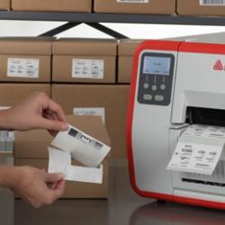
- Paper or film face label (smart label): the inlay is sandwiched between a printable face stock (paper or synthetic film) and adhesive on a liner. These are printed and encoded in RFID label printers.
When choosing an inlay, look at the antenna size and shape, the chip, the region tuning (865-867 MHz for India, or global 860-960 MHz), the recommended substrate, and the converter's performance data. Our UHF RFID labels page lists common inlay sizes.
Reader antennas: polarisation, gain and beamwidth
Circular vs linear polarisation
Polarisation describes the orientation of the radio wave's electric field. Most UHF tag antennas are linearly polarised dipoles: they respond best when aligned with the field.
- A linear polarised reader antenna radiates a field in one plane. A tag aligned with that plane gets maximum energy; a tag rotated 90 degrees gets very little and may not read at all.
- A circular polarised antenna rotates the field as it propagates, so a linear tag receives energy in any rotation around the antenna axis. The trade-off is roughly a 3 dB loss compared with a perfectly aligned linear antenna, which in free space means about 30% less range.
Use circular antennas where tag orientation varies - dock doors, conveyors, retail exits. Use linear antennas where tags are always oriented the same way - tags on a conveyor in a fixed position, vehicle windshields, shelves with consistently placed items. Circular antennas are specified as right- or left-hand circular (RHCP/LHCP); for most applications either works with linear tags.
Gain
Gain measures how strongly the antenna focuses energy in its main direction compared with a reference. Linear antenna gain is quoted in dBi (relative to an isotropic radiator); circular antenna gain is often quoted in dBic. Gain is not free energy: a higher gain antenna concentrates power into a narrower beam. Typical UHF panel antennas range from a few dBi for small near-field or shelf antennas to around 8-9 dBic for standard portal panels and higher for long-range directional antennas.
Beamwidth
Beamwidth (usually the -3 dB beamwidth) is the angle over which the antenna delivers at least half its peak power. Higher gain means narrower beamwidth. A wide-beam antenna covers a dock door from close range; a narrow-beam antenna reaches a vehicle lane further away without spilling into neighbouring areas.
Regulatory power limits
Regulations limit radiated power, not just reader output. India's de-licensed 865-867 MHz band (governed by WPC notifications) allows up to 4 W EIRP (1 W transmitter power); Europe's ETSI rules allow 2 W ERP in a similar band; the USA FCC rules allow 4 W EIRP in 902-928 MHz. Radiated power is calculated as reader output plus antenna gain minus cable loss. If you add a higher gain antenna, you may need to lower reader output to stay within the limit.
Near-field and far-field antennas
Around any antenna there is a near-field region, dominated by magnetic and electric fields stored close to the antenna, and a far-field region, where a propagating wave has formed. At UHF the boundary is only a few centimetres to a few tens of centimetres from a small antenna (it grows with antenna size).
- Far-field antennas (standard panels) are for reading at a distance: dock doors, ceilings, vehicle lanes, warehouse portals.
- Near-field antennas create a strong, contained field just above their surface. They are used in smart shelves, point-of-sale pads, desktop encoders and pharmaceutical lines where you must read only the items in a small zone and avoid stray reads.
Common antenna formats
| Format | Typical use | Notes |
|---|---|---|
| Portal / panel antenna | Dock doors, gates, conveyor tunnels | Usually circular, mid-to-high gain, mounted in pairs or more |
| Ceiling antenna | Retail floors, overhead zones | Low-profile, often wide beam; sometimes steerable array systems |
| Shelf / mat antenna | Smart shelves, cabinets, counters | Low power, near-field or short-range far-field |
| Long-range directional | Vehicle access, yards | High gain, narrow beam, often linear |
| Embedded / module antenna | Handhelds, desktop readers, kiosks | Integrated in the device housing |
Browse the formats we supply on our RFID antennas page.
Cables, connectors and loss
Every connector and metre of coaxial cable between the reader and antenna loses some power - in both directions, since the tag's weak reply returns through the same cable. Loss is cumulative in dB, and each 3 dB of loss halves the power reaching the antenna.
- Cable type matters. Thin, flexible cables lose much more per metre at UHF than thicker low-loss cables. As a rough guide, thin cables can lose around 0.3-0.5 dB per metre at 900 MHz, while thick low-loss cables (such as LMR-400 class) lose closer to 0.1-0.15 dB per metre.
- Keep runs short. Mount the reader close to its antennas rather than running long cables back to a rack.
- Connectors: readers commonly use reverse-polarity TNC (RP-TNC) or SMA connectors; antennas often use N-type, TNC or SMA. Use the right cable ends rather than chains of adapters, each of which adds loss.
- Weatherproof outdoor joints and avoid sharp bends or crushing, which damage cable and raise loss.
Antenna placement tips
- Face the antenna toward where tags will be, not toward where you hope they will be. Consider the height of tags on cartons and people.
- Use multiple antennas for portals - typically two to four per dock door, on both sides or above - so tags facing any direction are covered.
- Keep antennas away from large metal objects directly in front of them, and be aware that metal racks and doors cause reflections that extend or distort read zones.
- Separate neighbouring read zones by distance, angle, lower power or RF-absorbing material to prevent stray reads from the next door or lane.
- Mount rigidly. Antennas that move or vibrate create unpredictable zones.
- Test with real tagged items at the actual speeds and orientations, and adjust power and angle before fixing the installation. Our site survey chapter explains how.
Antennas work together with readers - the next chapter, RFID Readers Explained, covers the electronics that drive them.
Help India adopt this fast-growing technology - teach, consult or build projects with Indian RFID.
Frequently asked questions
What is the difference between an RFID inlay and an RFID tag?
An inlay is the bare functional part: a chip bonded to an antenna on a thin plastic film. A tag or label is an inlay that has been converted into a usable product, for example with a printable face, adhesive and liner or a protective case.
Should I use a circular or linear polarised reader antenna?
Use circular polarisation when tag orientation is unpredictable, such as cartons on a conveyor or people carrying items. Use linear polarisation when tags always face the same way, because it gives extra range and a more controlled read zone.
Does a higher gain antenna always read further?
It concentrates energy into a narrower beam, so it reads further along that beam but covers less area. Regulatory ERP or EIRP limits may also require you to reduce reader power when using a higher gain antenna.
Why does my UHF tag not read on a metal surface?
Metal shifts the tag antenna away from its design frequency and shorts out the electric field near the surface. Use an on-metal tag that includes a spacer or is designed to use the metal as part of the antenna.
How long can the cable between reader and antenna be?
There is no fixed limit, but every metre adds loss. Keep cables as short as practical and use low-loss coaxial cable for longer runs so that losses stay at a few dB at most.
Join the 1-month Certified RFID Specialist Program - live online. New batch 12 January 2027.