Types of RFID Reader Antennas (and How to Choose)
The reader antenna decides where, how far and how reliably tags are read. This chapter walks through every common reader antenna type from LF pads to UHF portals, ceiling arrays and long-range toll antennas, explains the specifications on a datasheet, and gives practical tables for selection, placement and troubleshooting.
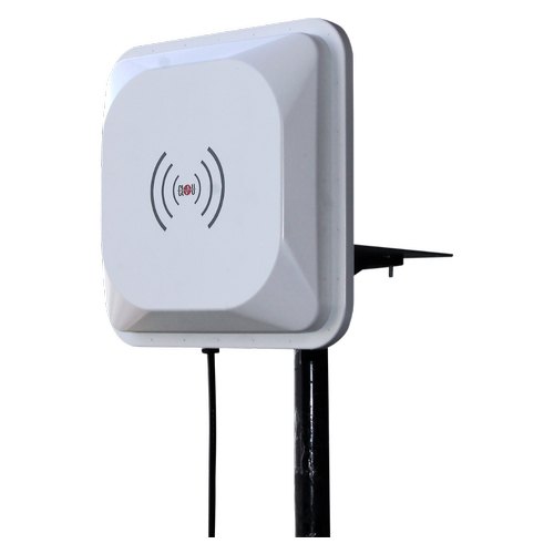
- The reader antenna radiates energy and commands to tags and receives their weak replies; it shapes the read zone more than any other part.
- LF and HF systems use loop antennas that couple magnetically over short distances; UHF systems use panel, patch and other far-field or near-field antennas.
- Circular polarisation tolerates random tag orientation; linear polarisation gives more range and a tighter zone when orientation is fixed.
- Gain, beamwidth, polarisation, VSWR, connector and IP rating are the key specs; reader power, cable loss and antenna gain together must stay within the regional EIRP or ERP limit.
- Placement, angles, shielding and cable quality decide real-world performance - always test on site with real tags and real items.
What a reader antenna actually does
Every RFID system has two antennas in the conversation: one on the tag and one on the reader. The reader antenna is the part that turns the reader's electrical signal into a radio field, sends commands into that field and then listens for the very weak replies coming back from tags. When people say a reader "reads" or "decodes" a tag, it is the reader antenna that physically catches the signal; the reader electronics then demodulate and decode it.
The tag antenna is the other half. It captures energy to power the chip and reflects (backscatters) the reply. Tag antennas, inlays and how they are tuned are covered in RFID Antennas & Inlays. This chapter focuses only on the reader side: the antennas you mount on walls, doors, ceilings, shelves, conveyors and vehicles.
Why does it matter so much? Because in a passive system the reader antenna defines the read zone: its shape, length, width and the direction it points. In practice, most "the reader is not working" complaints turn out to be antenna selection, placement or cabling issues.
New to readers? Start with RFID Readers Explained.
LF and HF reader antennas: loops, pads and gates
Low frequency (125-134 kHz) and high frequency (13.56 MHz) systems work mainly through magnetic (inductive) coupling. The reader antenna is a coil or loop of wire, and the tag antenna is another coil. When the two loops are close and roughly parallel, energy and data pass between them like a loosely coupled transformer. This is why LF and HF read ranges are short - typically from touching distance up to tens of centimetres, and up to about a metre with large HF gate antennas.
Desktop pads
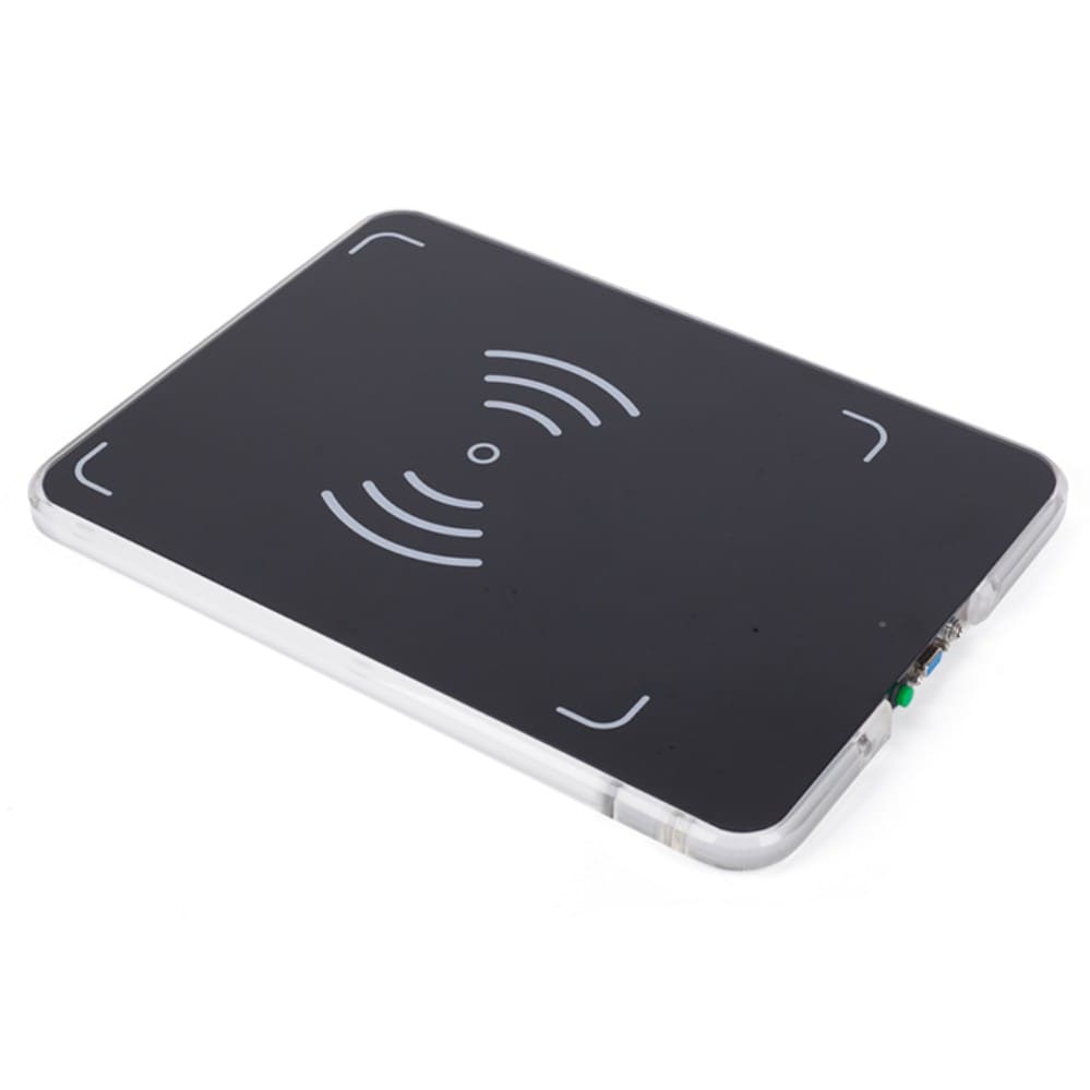
A desktop pad is a flat loop antenna, often built into a small reader, that reads cards, library books, lab samples or NFC tags placed on top of it. Pads are used at library issue counters, access control enrolment desks, hospital sample stations and NFC encoding stations. The read zone is a shallow bubble above the pad.
Panel and shelf antennas
Larger HF loop panels sit under shelves, inside cabinets or under tables to read many items placed on them, for example files, books or medicine boxes using ISO/IEC 15693 tags.
Gate antennas
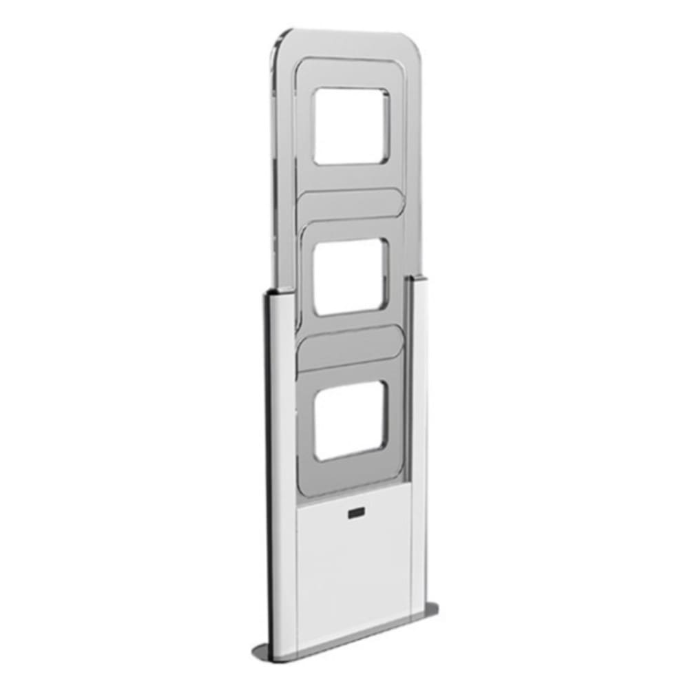
Library and retail security gates use pairs of large HF or UHF loop or panel antennas on either side of an aisle. For HF, the loops are often designed with figure-of-eight or multi-loop patterns so that tags are detected in several orientations as people walk through.
In the real world
UHF reader antenna types
UHF RFID (860-960 MHz worldwide; 865-867 MHz in India) works mainly in the far field: the antenna launches an electromagnetic wave that travels several metres. This gives longer range and many more antenna shapes. The main families are below.
Circularly polarised panel / patch antennas
The workhorse of UHF RFID. A square or rectangular flat panel, typically 20-30 cm on a side, with a patch radiator inside. The field rotates as it travels, so tags are read in almost any rotation around the beam axis. Used for dock doors, conveyors and most general installations.
Linearly polarised antennas
The field oscillates in one plane (horizontal or vertical). When the tag is aligned with that plane, a linear antenna gives more range than a circular antenna of similar gain, because circular antennas lose about 3 dB to a linearly polarised tag. When the tag is rotated 90 degrees, the read can fail completely. Use linear antennas when you control orientation: conveyors with labels always vertical, tyre lines, vehicle windscreen tags or racks where all tags face the same way.
Far-field vs near-field antennas
Far-field antennas are designed to radiate energy away to read tags metres away. Near-field UHF antennas are designed to create a strong, mostly magnetic or reactive field just above the surface - typically a few centimetres - and very little radiated energy. They are used for:
- Desk and point-of-sale readers that must read one item without picking up the whole basket.
- Encoder couplers inside RFID printers and encoding stations, which write one label at a time on a moving roll. The coupler is a tiny near-field antenna positioned precisely under the label path. See RFID Encoders Explained.
- Item-level shelves in jewellery, pharmacy or retail, where each shelf must read only its own items.
Ceiling and overhead antennas
Low-profile, wide-beam antennas mounted on the ceiling, usually 3-6 m high, pointing down. They cover a floor zone in a retail store, warehouse aisle or hospital corridor.
Portal and dock-door antenna pairs
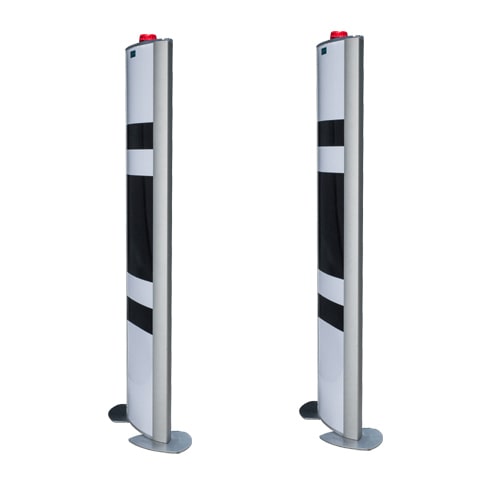
Two to four panels mounted on both sides (and sometimes above) a dock door, gate or passage. Pallets, trolleys or people pass through, and all antennas read together to cover tags on every face of the load.
Tunnel and box antennas
A shielded enclosure with antennas on several inner walls. Cartons, totes or garment bundles move through on a conveyor or are placed inside, and every tag is read while stray reads from outside are blocked. Popular in apparel distribution.
Shelf and smart-cabinet antennas
Thin antennas built into shelves, drawers or cabinets that read the items stored on them. Smart cabinets for tools, medicines, surgical kits or documents use several small antennas, a multiplexer and shielded walls so that each cabinet only reads its own contents.
Mat and floor antennas
Ruggedised flat antennas placed on or under the floor, pointing upward. They are used where side or overhead mounting is impossible, such as sports timing (shoe or bib tags), entry lanes, or under a work surface.
Integrated reader-antennas (all-in-one)
A reader and antenna in one enclosure, normally with Ethernet, PoE, serial or Wiegand output. Easier to install and cheaper for single-point applications like a parking gate or a single conveyor point, but less flexible because you cannot add more antennas or move them independently.
Handheld built-in antennas
Handheld readers carry their own antenna, usually circular or a switchable pattern, sized for the device. Range is shorter than fixed systems because the antenna is small and power is limited by the battery.
Wearable antennas
Small wrist or glove antennas paired with compact readers keep hands free for picking and maintenance work.
Ruggedised outdoor and long-range high-gain antennas
Weatherproof antennas (often IP65-IP67) with higher gain and narrower beams for vehicle access, yard management, rail and toll lanes. Vehicle tags on windscreens are read at several metres as the vehicle approaches. India's FASTag lanes are a good example - see How FASTag Works in India.
Phased-array, beam-steering and location antennas
Some advanced antennas contain many radiating elements whose signals are combined electronically. By changing the phase of each element, the system can steer the beam in different directions without moving parts. Combined with signal strength and phase measurements, these arrays can estimate where a tag is and in which direction it is moving. RAIN (UHF) location systems use this approach to track items across a store or warehouse floor. Accuracy depends heavily on the environment, so treat published figures as typical.
Key specifications on an antenna datasheet
| Spec | What it means | What to look for |
|---|---|---|
| Frequency band | Range of frequencies the antenna is tuned for | Must cover your region: 865-867 MHz in India and Europe-style bands, 902-928 MHz in the USA. Many antennas are "global" 860-960 MHz but perform best in part of it. |
| Gain (dBi / dBic) | How strongly the antenna focuses energy in its main direction compared with an ideal isotropic radiator. dBic is gain referenced to a circularly polarised isotropic antenna. | Typical UHF panels are about 6-9 dBic; near-field and small antennas are much lower; long-range antennas can be 10-12 dBi or more. |
| Polarisation | Orientation of the electric field: linear (vertical or horizontal) or circular (right- or left-hand) | Circular for random tag orientation; linear for fixed orientation and extra range. |
| Beamwidth | Angle of the main lobe where power is within 3 dB of the peak | Wide (around 60-100 degrees) to cover an area; narrow (around 30-40 degrees) for focused or long-range reads. |
| Axial ratio | How "circular" a circular antenna really is; 0 dB is perfect | Lower is better; typically below about 2-3 dB for a good circular panel. |
| VSWR / return loss | How well the antenna is matched to the 50-ohm cable; mismatch reflects power back to the reader | VSWR below about 1.5:1 (return loss better than about 14 dB) across the band is good. |
| Connector | RF connector type | RP-TNC is common on readers, N-type on rugged outdoor antennas, SMA on small or embedded units. Match connectors; avoid stacks of adapters. |
| IP rating | Dust and water protection | IP54 indoor general use; IP65-IP67 outdoor, wash-down or cold-store. |
| Size and weight | Physical dimensions | Larger antennas usually give more gain and narrower beams; small antennas fit shelves and handhelds. |
How gain and EIRP interact with regulations
Regulators do not limit the antenna alone; they limit the radiated power that leaves it. That is expressed as EIRP (Effective Isotropic Radiated Power) or ERP (Effective Radiated Power, referenced to a dipole; ERP = EIRP minus 2.15 dB). A simple budget is:
EIRP (dBm) = reader output power (dBm) - cable and connector loss (dB) + antenna gain (dBi)
In India, UHF RFID in 865-867 MHz is permitted up to 4 W EIRP with a maximum of 1 W (30 dBm) transmitter power, under WPC rules. Europe uses 2 W ERP in its 865-868 MHz band, and the USA allows 4 W EIRP in 902-928 MHz. Rules are revised from time to time, so always confirm the current notification before finalising a design.
Higher gain does not create energy; it concentrates the same power into a narrower beam, so within an EIRP cap it does not make the system more powerful overall. What higher gain does help with is the receive side: the antenna collects more of the tag's weak reply from its main direction.
Cabling, losses and multiplexers
Coaxial cable between reader and antenna loses energy in both directions: on the way out to the tag and on the way back. At UHF, thin cables can lose around 0.5 dB or more per metre, while thicker low-loss cables lose much less. A 3 dB loss halves the power reaching the antenna and also halves the reply coming back.
- Keep cables as short as practical; mount the reader close to the antennas.
- Use low-loss 50-ohm cable for runs longer than a few metres, and thin flexible cable only for short jumpers.
- Minimise connectors and adapters; each one adds a little loss and a possible failure point.
- Do not bend cables tighter than their rated bend radius and protect them from forklifts and crushing.
Most fixed readers have 1, 2, 4 or 8 antenna ports. To connect more antennas, use an RF multiplexer, which switches one reader port across many antennas in turn. Multiplexers are common in smart shelves and cabinets. The trade-off is that each antenna is active only part of the time, and each multiplexer adds some insertion loss. See our RFID antenna range for typical panel, near-field and rugged models, and RFID Read Range for the full link budget.
Mounting and placement patterns
Dock-door portals
The classic portal uses two antennas on each side of the door, one at about 1 m and one at about 2 m high, angled slightly inward and slightly toward the direction pallets come from. This covers tags at the bottom and top of a pallet on both faces. Some designs add an overhead antenna for tall loads.
Conveyors
Mount one or two circular panels above or beside the belt, angled about 30-45 degrees against the flow so the tag is seen for longer. Use a photo-eye trigger so the reader only transmits when a carton is present, and shield adjacent lines to avoid cross-reads.
Overhead and zone coverage
Ceiling antennas are spaced so their coverage circles overlap slightly on the floor. Height, beamwidth and the height of the tagged items decide spacing; plan it with a site survey rather than a formula alone.
Shielding and RF absorbers
UHF energy reflects off metal floors, walls, racks and vehicles, which can create both dead spots and unwanted reads far outside the intended zone. Tools to control this include metal shields behind or beside antennas, RF absorber foam on reflective surfaces, reducing power to the minimum that reads reliably, and using reader features such as RSSI filtering and read-zone logic. Details on testing are in RFID Site Survey & Testing.
Antenna selection by application
| Application | Antenna type | Notes |
|---|---|---|
| Library issue counter | HF desktop pad | Short range, reads a stack of books; ISO/IEC 15693 tags. |
| Library / store exit | HF or UHF gate antennas | Pairs on both sides of an aisle; tune for walking speed. |
| Warehouse dock door | 2-4 circular UHF panels | Two heights, both sides, angled; shield between doors. |
| Conveyor / sortation | 1-2 circular panels or tunnel | Angle against flow; photo-eye trigger; shield neighbours. |
| Carton / garment verification | Tunnel or box antenna | Shielded enclosure for 100% reads without strays. |
| Retail point of sale | Near-field UHF desk antenna | Reads only items on the counter, not the queue. |
| Label encoding | Near-field coupler | Inside printer or encoder; one label at a time. |
| Jewellery / pharmacy shelf | Near-field shelf antennas + multiplexer | Item-level reads per shelf or tray. |
| Store or aisle zone tracking | Ceiling or phased-array antenna | Overlapping coverage; location estimates are approximate. |
| Vehicle access / toll | Rugged linear or circular high-gain antenna | Aimed at windscreen tags; outdoor IP rating; mind EIRP. |
| Sports timing | Mat / floor antennas | Read shoe or bib tags as runners cross. |
| Single-point gate or kiosk | Integrated reader-antenna | Simple install; limited expansion. |
Troubleshooting antenna problems
| Symptom | Likely cause | Fix |
|---|---|---|
| Short range on all tags | High cable loss, wrong band antenna, low power setting | Measure or replace cable; confirm antenna covers 865-867 MHz; check reader power and region setting. |
| Reader reports high reflected power or antenna fault | Loose or damaged connector, crushed cable, bad adapter | Inspect and reseat connectors; replace cable; remove unnecessary adapters. |
| Tags read in some orientations only | Linear antenna with rotating tags | Switch to circular polarisation or add a second antenna at 90 degrees. |
| Reads from the next dock, aisle or conveyor | Too much power, reflections, no shielding | Reduce power, re-angle antennas, add shields or absorber, use RSSI filtering. |
| Missed tags in the middle of pallets | Liquids or metal blocking, too few antennas | Add antennas, tag outer faces, slow the forklift, use better tags for the product. |
| Intermittent reads outdoors | Water ingress in connectors, temperature cycling | Weatherproof joints, use N-type outdoor connectors and IP67 antennas. |
| Near-field station reads neighbouring items | Power too high turning it into a far-field reader | Lower power, add separation, check that a true near-field antenna is used. |
Choosing and placing antennas is a skill that improves with hands-on practice. If you want structured, practical training on readers, antennas and site surveys, the RFID courses in India from Indian RFID cover this in depth.
Help India adopt this fast-growing technology - teach, consult or build projects with Indian RFID.
Frequently asked questions
What is the difference between a reader antenna and a tag antenna?
The reader antenna is connected to the reader by a cable (or built into it) and radiates energy and commands. The tag antenna is part of the tag, captures that energy to power the chip and reflects a reply back to the reader antenna.
How many antennas does a dock-door portal need?
Most dock-door portals use two to four antennas, typically two on each side of the door. Small doors with slow pallet movement may work with two; large doors, fast forklifts or dense mixed loads usually need four.
Can I connect any UHF antenna to any UHF reader?
Only if the frequency band, connector and impedance (normally 50 ohms) match and the total EIRP stays within regulations. Check that the antenna covers your regional band, for example 865-867 MHz in India, and use the correct cable and adapters.
Is a higher gain antenna always better?
No. Higher gain gives a narrower, longer beam, which suits long-range or focused reads but covers less area. In regulated bands you may also need to reduce reader power so that EIRP stays within the legal limit.
What is a near-field UHF antenna used for?
Near-field antennas create a strong field only within a few centimetres, so they read or encode a single item without picking up neighbours. They are used on desks, in printers and encoders, at point of sale and in some item-level shelf systems.
Join the 1-month Certified RFID Specialist Program - live online. New batch 12 January 2027.