Fixed RFID Reader Installation: Accessories & Read Direction
A fixed RFID reader is only one part of a working read point. This chapter lists every accessory a fixed reader installation needs, gives starter kits for common sites, explains the three meanings of read direction and walks through installation, commissioning and the mistakes that cause most field problems.
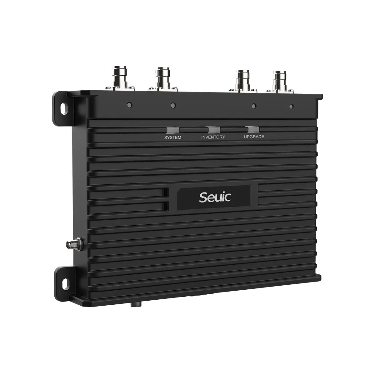
- A fixed read point needs antennas, low-loss cables, matching connectors, mounts, power, network, sensors, software and spares - not just a reader.
- Keep antenna cables as short as practical; every 3 dB of cable loss halves the power reaching the antenna.
- Direction of travel is detected with two read zones (outer and inner antennas) plus timestamp order, RSSI trends and photo-eye confirmation.
- Use circular polarisation when tag orientation is unknown and linear polarisation when it is fixed and you need extra range.
- In India, configure the reader for 865-867 MHz and keep the radiated power within 4 W EIRP (1 W transmitter output).
A read point is a system, not a box
When people buy a fixed RFID reader, they often expect it to work like a barcode scanner: plug it in and start reading. In reality the reader is the radio and the brain, but the performance of the read point depends on everything around it - antennas, cables, mounting height, trigger sensors, software settings and even the metal racks near the door. A good reader with the wrong cable or a badly aimed antenna will perform worse than a modest reader that is installed properly.
This chapter answers the two questions we hear most often from project teams: what accessories does a fixed reader need, and which reader setup suits which direction. It then covers the installation steps, a commissioning checklist and the mistakes that cause most field problems.
Accessories checklist for a fixed reader
Use this table as a bill-of-materials checklist. Not every site needs every line, but every line should be consciously decided.
| Item | Purpose | What to specify | Notes |
|---|---|---|---|
| Reader antennas | Radiate the reader's energy and receive tag replies | Number per reader (one per port used), gain, beam width, circular or linear polarisation, indoor/outdoor rating | Typical portals use 2-4 antennas; see RFID antennas |
| RF coaxial cables | Carry RF between reader port and antenna | Low-loss 50-ohm cable (LMR-195, LMR-240 or LMR-400 class), exact length, connectors fitted at both ends | Thicker cable = lower loss but stiffer and harder to route |
| Connectors and adapters | Join cable to reader and antenna | Check the reader port (often RP-TNC) and the antenna (often N-type or SMA, sometimes RP-TNC) | Avoid stacking adapters; each joint adds a little loss |
| Antenna brackets and poles | Hold antennas at the right height and angle | Wall, pole or ceiling mounts with tilt/swivel adjustment; floor stands for portals | Must allow re-aiming during tuning |
| Reader enclosure | Protects reader from dust, water, impact and tampering | NEMA 4X or IP65/IP66 box for outdoor or wash-down areas; lockable for public areas | Plan ventilation and cable glands |
| Power | Runs the reader | PoE (802.3af) or PoE+ (802.3at) switch or injector, or the DC adapter; UPS for critical points | Many readers need PoE+ for full RF power or to drive GPIO loads |
| Network | Connects reader to software | Cat6 Ethernet cabling, switch port, VLAN/IP plan; Wi-Fi or 4G gateway where cabling is impossible | Wired Ethernet is the most reliable option |
| GPIO trigger sensors | Start and stop reading only when something is present | Photo-eyes, motion or presence sensors, loop detectors for vehicles; voltage and wiring type | Reduces stray reads and RF noise |
| GPIO outputs | Give feedback to operators | Stack lights, buzzers, displays, relay to a boom barrier or conveyor diverter | Check GPIO current rating; use relays for bigger loads |
| Multiplexer | Adds antenna ports to a reader | Number of extra ports, compatibility with the reader | Ports are read in turn, so each one gets less read time |
| Surge arrestors and grounding | Protect reader from lightning and surges | Inline coaxial arrestor per outdoor antenna, proper earth, surge protection on power and Ethernet | Essential for any outdoor gate or toll-type install |
| RF absorber / shielding panels | Control stray reads from neighbouring doors or stock | Absorber foam or shielded panels sized for the zone | Often cheaper than fighting stray reads in software |
| Test tags and a handheld | Commissioning and troubleshooting | Tags identical to production tags; a UHF handheld set to the same region | Never tune with "demo" tags only |
| Software | Configure reader and process reads | Reader management tool, middleware or edge app, licences, integration to WMS/ERP | See middleware and software |
| Cable management and labelling | Neat, safe, serviceable installation | Conduit, trays, ties, port and cable labels at both ends | Forklift-height cables get damaged |
| Spares | Fast recovery after a failure | Spare cable, antenna, PoE injector, sometimes a spare reader per site | Cheap insurance for critical lanes |
In the real world
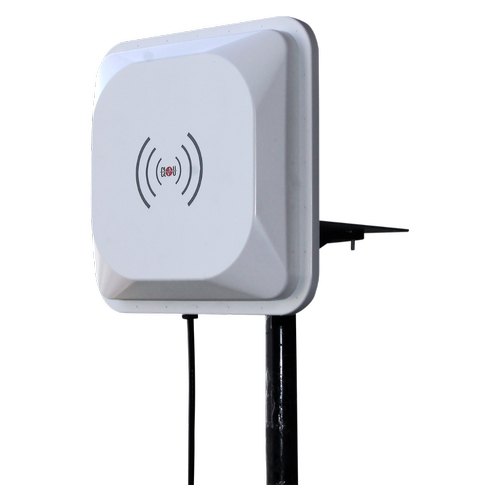
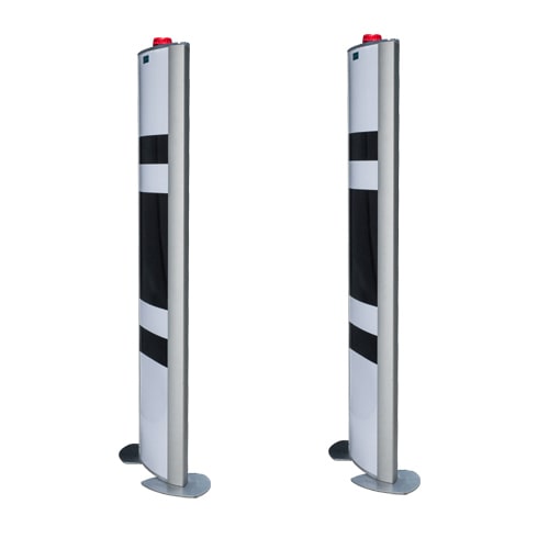
Starter kits for three common sites
These are typical starting points, not fixed designs. A site survey decides the final list. Costs vary widely with brand and quantity, so treat any figure as indicative only.
Dock door (pallets and cartons on forklifts)
- One 4-port fixed reader
- Four circular-polarised panel antennas (two outer, two inner, one pair on each side of the door)
- Four low-loss cables, LMR-240 class or better, cut to length with the right connectors
- Wall brackets or bollard-protected poles for the antennas
- PoE+ switch port or injector, Cat6 cable
- Two photo-eyes (inside and outside) and a stack light
- Middleware or edge app to tie reads to a shipment or receipt
- Absorber panels if adjacent doors are less than a few metres apart
Store exit (people carrying tagged goods)
- One 2- or 4-port reader, or an overhead integrated reader above the doorway
- Two or more slim pedestal or ceiling antennas, circular polarised
- Presence or motion sensor, plus buzzer and light for alarm events
- Lockable enclosure or concealed mounting, PoE power
- Software that checks each read against sold status in the POS
Vehicle gate (windscreen tags)
- One reader per lane (or one multi-port reader serving entry and exit lanes)
- One high-gain directional antenna per lane, outdoor rated
- Pole or gantry mount, outdoor reader enclosure
- Coaxial surge arrestor per antenna, proper earthing, surge protection on power
- Vehicle loop detector or presence sensor as a trigger
- Relay output to the boom barrier, UPS, and an optional display
Read direction (1): detecting in versus out
"Direction" means three different things in RFID. The first is direction of travel: did the pallet go into the warehouse or out of it? A single antenna cannot tell; it only knows a tag was nearby. To infer direction you need at least two read zones and some logic.
Two zones with inner and outer antennas
Place one antenna pair on the outside face of the door and another pair on the inside, connected to different reader ports. When a tag is first seen by the outer pair and later by the inner pair, it moved inward. Software compares the first-seen timestamps of each zone, and the order of zone transitions, to decide.
RSSI trends
RSSI (received signal strength) rises as a tag approaches an antenna and falls as it moves away. Watching RSSI per antenna over a second or two gives a second opinion: if outer-zone RSSI peaks before inner-zone RSSI, the tag moved inward. RSSI alone is noisy, so use it to support timestamp logic, not replace it.
Overhead phased-array readers
Some overhead RFID readers use a steerable beam array mounted on the ceiling. They sweep the beam across zones on either side of a doorway and can infer the direction of movement internally, reporting tags as having moved in or out. They reduce cabling but need careful mounting height and ceiling access.
Confirming with sensors
Photo-eyes on both sides of the door give a physical record of what crossed and in which order. Combining "beam A broke before beam B" with the RFID zone order gives a very reliable direction decision, and also tells you when a forklift passed with no tag reads at all.
Read direction (2) and (3): antenna aiming and polarisation
Aiming and coverage direction
The second meaning of direction is where the antenna points and how wide its beam is. Choose the antenna pattern to match the zone:
- Directional high-gain, narrow-beam antennas concentrate energy in one direction for long range. They suit vehicle lanes and tolling, where the tag is several metres away and neighbouring lanes must be ignored.
- Wider-beam panel antennas cover a doorway or portal from the sides, reading tags anywhere across the opening.
- Near-field antennas read only within a few centimetres, for item-level reading on a counter, a shelf or a conveyor spot where you must not read the next item.
- Ceiling or overhead downward-facing antennas create a zone below them, useful for corridors, rooms and areas where side-mounted antennas would be in the way.
Tag orientation versus antenna polarisation
The third meaning is the orientation of the tag relative to the antenna. Most UHF tags are linearly polarised dipoles. A linear antenna reads them strongly when they are aligned with it and poorly when they are turned 90 degrees. A circular antenna radiates a rotating field, so it reads tags in any rotation, at the cost of roughly 3 dB compared with a perfectly aligned linear antenna.
- Circular polarisation - unknown or random orientation: cartons, garments, people, mixed pallets.
- Linear polarisation - known orientation and a need for extra range: windscreen tags, tags in a fixed position on returnable containers.
For more on how orientation, gain and power trade against each other, see the RFID read range chapter.
Which setup suits which direction
| Application / direction need | Recommended reader + antenna setup | Mounting | Notes |
|---|---|---|---|
| Dock door, in vs out | 4-port fixed reader, 2 outer + 2 inner circular panels, or an overhead direction-aware reader | Both sides of the door at roughly 1-2 m height, angled into the opening | Add photo-eyes both sides; absorber between close doors |
| Store exit | 2-4 port reader with pedestal or ceiling antennas, or an overhead reader | Pedestals at the doorway or concealed in ceiling | Direction logic avoids alarming on goods coming back in |
| Conveyor, one direction | 1-2 port reader, small circular or linear antennas in a tunnel | Above and/or beside the belt, often in a shielded tunnel | Direction is fixed; trigger with a photo-eye, control spacing |
| Vehicle gate, entry vs exit lanes | One high-gain directional antenna per lane, separate reader port or reader per lane | Pole or gantry, aimed down the lane at the windscreen | Lane identity gives direction; loop sensor as trigger |
| Corridor / room entry | Overhead reader or two ceiling antennas forming two zones | Ceiling, facing down, on each side of the doorway | Works for staff badges and asset movement |
| Marathon finish line | Multi-port reader, mats or side antennas across the line - see RFID race timing | Floor mats or low side stands at the timing line | Direction is known; the challenge is timing accuracy in dense crowds |
| Toll lane | Lane reader with narrow-beam antenna - see FASTag and RFID in India | Overhead gantry above each lane | Tight beam prevents reading the adjacent lane |
Installation steps
- Survey. Measure the zone, note metal, liquids and neighbouring read points, check for RF interference and confirm power and network locations. The site survey chapter covers this in depth.
- Mount. Fix brackets and antennas at the planned heights and angles, leaving room to adjust. Protect antennas from forklifts with bollards or guards.
- Cable. Run coaxial cables in conduit or trays, avoid sharp bends, tighten connectors firmly and label both ends with the port number.
- Power up. Connect PoE or DC power, then the network. Confirm the reader boots and is reachable at its planned IP address.
- Configure. Set the region to India (865-867 MHz), set transmit power per port so that the EIRP stays within 4 W, choose the session (S0-S3) and target settings, enable only the ports in use, and set up GPIO triggers.
- Tune. Adjust power and antenna angles until the intended zone reads reliably and the areas outside it do not. Reduce power before adding absorber.
- Test with tags. Use real tagged products in their real packaging, at real speeds, in both directions, many times.
- Document. Record mounting heights, angles, cable lengths, power per port, firmware version and the final configuration file.
Commissioning checklist
- Region set to India and verified in the reader configuration
- Power per port recorded and EIRP within 4 W
- Every antenna port reads test tags; unused ports disabled
- Read rate measured with real loads in both directions (for example, 50 or more passes)
- Stray reads from adjacent doors, staging areas and racks checked and controlled
- Direction logic verified: in, out, stop-and-reverse and "drove through and backed out" cases
- GPIO sensors, lights, buzzers and relays tested
- Data arriving correctly in middleware and the business system (WMS, ERP, POS)
- Reader behaviour after power loss and network loss tested (buffering and recovery)
- Default passwords changed, firmware updated, configuration backed up
- As-built document and photographs handed over
Common mistakes and fixes
| Mistake | Symptom | Fix |
|---|---|---|
| Long, thin antenna cables | Short range, weak reads on far side of portal | Move reader closer or use lower-loss cable |
| Wrong region setting | Poor reads, compliance risk | Set India 865-867 MHz; use tags tuned for this band |
| Power set to maximum everywhere | Reads from neighbouring doors and stock | Reduce power per port, re-aim, add absorber |
| Reading continuously with no trigger | Floods of stray reads, staged pallets reported as moved | Use photo-eyes or presence sensors to gate reading |
| Single zone used for direction | Wrong in/out decisions | Add inner and outer zones plus sensor confirmation |
| Linear antenna with random tag orientation | Some items never read | Switch to circular polarisation |
| No surge protection outdoors | Reader or port fails after a storm | Add coaxial arrestors and proper earthing |
| Loose or mismatched connectors | Intermittent reads, high reflected power alarms | Use correct connectors, tighten, avoid adapter chains |
| Testing with demo tags only | Good pilot, poor production results | Commission with real tags on real products |
If you design or install read points regularly, the RFID courses in India from Indian RFID include hands-on practice with fixed reader setup, tuning and direction logic.
Watch & learn
Videos are from YouTube and their respective creators; they play only when you click.
Help India adopt this fast-growing technology - teach, consult or build projects with Indian RFID.
Frequently asked questions
What accessories are required for a fixed RFID reader?
At minimum: one or more antennas, low-loss coaxial cables with the correct connectors, antenna mounts, a power source (PoE/PoE+ or DC adapter), a network connection and configuration software. Most real sites also need trigger sensors, an enclosure, cable management, test tags and spares.
Can a single fixed reader tell whether an item is going in or out?
Yes, if it has two read zones. Antennas facing the outside and antennas facing the inside are connected to different ports, and software compares which zone saw the tag first and how the signal strength changed. Photo-eyes on both sides make the decision more reliable.
How long can an RFID antenna cable be?
There is no fixed limit, but loss grows with length. With thin cable you may lose several dB over 6-10 metres, so long runs should use a thicker low-loss cable or the reader should be moved closer to the antennas.
Should I use circular or linear polarised antennas?
Circular antennas read tags in almost any rotation and are the safe choice for cartons, people and mixed items. Linear antennas give more range but only when the tag is consistently aligned with the antenna, such as tags on a windscreen or a fixed position on a pallet.
What power level is allowed for UHF RFID readers in India?
In the 865-867 MHz band India allows up to 4 W EIRP, which corresponds to about 1 W of transmitter output into a typical antenna. Reader power, cable loss and antenna gain together decide the EIRP, so check the calculation for every port.
Join the 1-month Certified RFID Specialist Program - live online. New batch 12 January 2027.